|
|
 Harris
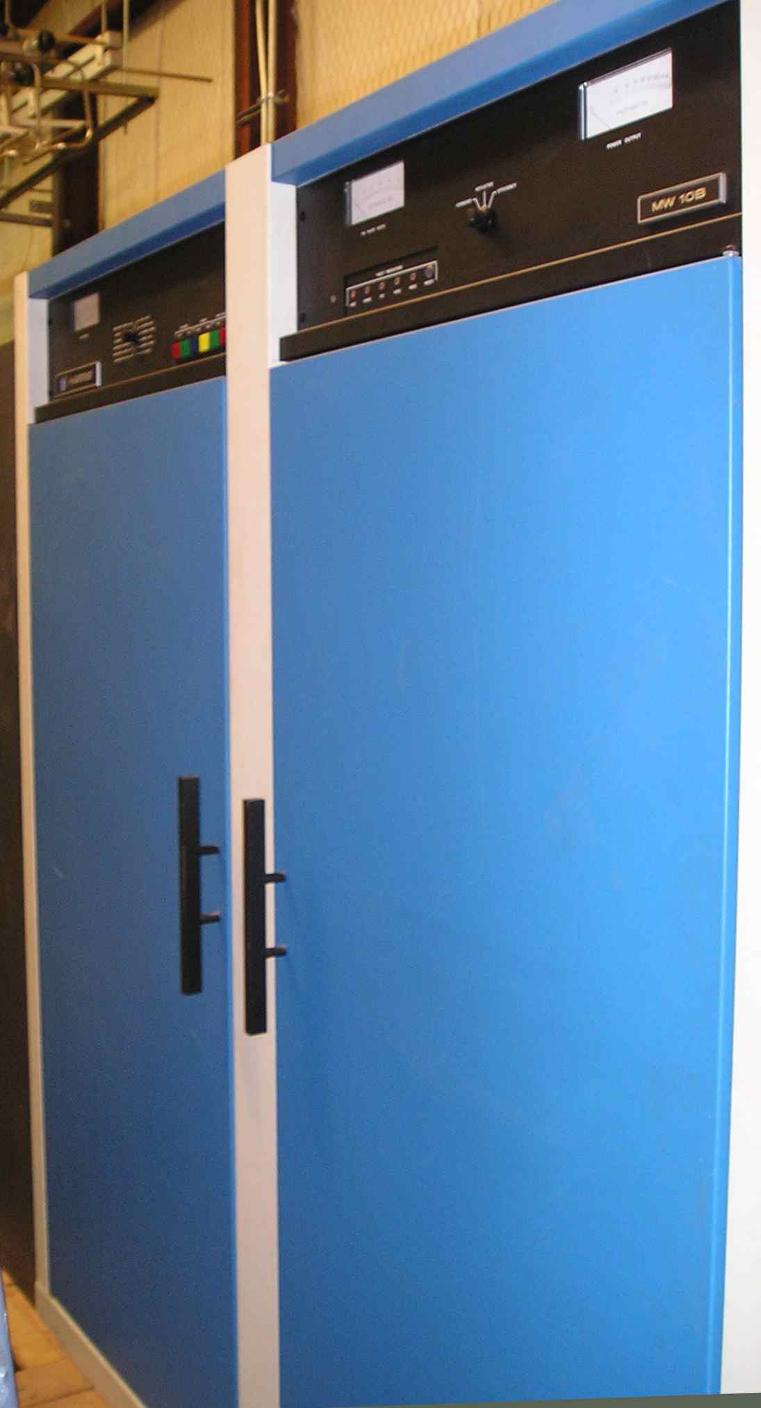
MW10B, 10 KW AM Transmitter Harris
MW10B, 10 KW AM Transmitter
POWER OUTPUT: (Rated) 10,000 watts. (Capable)
11,000 watts.
FCC type accepted at 10,000, 5000, 2500 and 1 000 watts.
MODULATION METHOD: Pulse Duration Modulation.
CARRIER SHIFT: (@ 95% modulation with 400 Hz tone) 2% or less.
AUDIO INPUT: (For 95% modulation) + 10 dBm, ±2 dB.
AUDIO INPUT IMPEDANCE: 600 ohms balanced.
AUDIO FREQUENCY RESPONSE: ±1 db, 20 to 10,000 Hz.(Response referred
to 1kHz, 95% modulation, with modulations at other frequencies held
to same percentage. Response may degrade at higher modulating
frequencies if transmitter is operated into a bandwidth limited
antenna system.)
THD DISTORTION: (1) 2% or less @ 95% modulation, 20 to 10,000 Hz
unenhanced.
RF HARMONICS: Meets or exceeds FCC and CCIR requirements.
SPURIOUS OUTPUT: - 80 dB or better.
RF FREQUENCY RANGE: 535 to 1605 kHz. Supplied to one frequency as
ordered.
RF OUTPUT IMPEDANCE: 50 ohms, unbalanced. Other output impedances
available on special order.
RF OUTPUT CONNECTOR: 1 5/8” inch male EIA flange. Other types of
output connectors available on special order.
MAXIMUM VSWR: 1.3 to 1.
NOISE: (2) Unweighted, 60 dB below 100% modulation. Weighted (CCIR
Rec. 468-1), 70 dB below I 00% modulation.
POSITIVE PEAK CAPABILITY: 125% at 11 kW output, when modulated with
processed program type material.
NEGATIVE PEAK CAPABILITY: 95%.
FREQUENCY STABILITY: ±20 Hz or less over operating temperature
range.
SUPPLY VOLTAGE: 200/500 volts, 3 phase, 60 Hz, closed delta/wye or
350/430 volts, 3 phase, 50 Hz, 4 wire wye.
LINE VOLTAGE REGULATION AND VARIATION: 5% maximum.
LINE VOLTAGE UNBALANCE: (2) 24% maximum
POWER CONSUMPTION (10 kW Carrier): (3) (Typical) 20.5 kW, 0%
modulation; 22.1 kW, 50% tone modulation; 28.0 kW, 100% tone
modulation. (Maximum) 22.1 kW, 0% modulation; 24.3 kW, 50% tone
modulation; 30.8 kW, I 00% tone modulation.
POWER FACTOR: 95% or better.
AMBIENT TEMPERATURE RANGE: (4) -20° to ±50°C (- 4° to + 122°F) at
sea
level. Decreases 3.5° per 1,000 feet of altitude (84°F at 10,000
feet).
MAXIMUM RELATIVE HUMIDITY: 95%.
MAXIMUM ALTITUDE FOR FULL POWER RATING: 10,000 feet AMSL (3048
meters). Transmitters for operation above 10,000 feet AMSL require
special order.
SIZE: (5) 78" H x 72 " W x 32" D (198 cm x 183 cm x 81.3 cm).
WEIGHT: Unpacked, 1500 lbs. (680.4 kg) - approximate. Domestic
packed, 1900 lbs. (861.8 kg) - approximate. Export packed, 2150 lbs.
(975.2 kg) approximate.
CUBAGE: 120 cu. ft. (3.4 cu. meters) packed - approximate.
FINISH: Blue, white and black.
TUBES USED: One (1) 3CX 1 5,00OH3 and one (1) 4CX 15,OOOA.
REMOTE CONTROL: Normal terminal board interface.
(1) Distortion measured at 95% modulation, or less, down to 25%. If
transmitter is operated into a bandwidth limited antenna system,
distortion at the higher modulating frequencies may degrade.
(2) Noise measured over the band 20 Hz to 20 kHz, with line to line
voltages of the supply line balanced. Noise may degrade to 56 dB
below 100% modulation with line voltage unbalance not exceeding 4%.
(3) Typical power consumption figures are for 10 kilowatts output
and for optimum transmitter adjustment. For higher output powers
and/or transmitter misadjustments, power consumption may be higher.
(4) Maximum operating temperature derates linearly to +29°C (84.2°F)
at 10,000 feet AMSL (3048 meters).
(5) Does not include height of output connector, which may be
removed for transport.
|