|
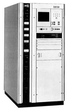
BE FM
5B & 3.5B TECHNICAL SPECIFICATIONS
GENERAL
Power Output:
FM3.5B, 3.5 kW (1.5 to 3.8 kW); FM5B & FM5B/S, 5 kW (2.5 to 5.5
kW)
Frequency
Range: 87.5 to 108 MHz, tuned to specific operating frequency;
exciter programmable in 10 kHz steps
RF Output
Impedance: 50 ohm (others on special request)
Output
Connector: 1
5/8" EIA flange
VSWR:
FM3.5B, 2:1 maximum, FM5B & FM5B/S, 1.8:1 maximum (all will operate
into higher VSWR with automatic power reduction)
Frequency
Stability: ±300 Hz, 0° to 50° C
Type of
Modulation: Direct frequency modulation of carrier frequency
Modulation
Capability: ±350 kHz
Modulation
Indication: Peak reading, color coded, LED display with baseband
overmodulation indicator
Exciter:
Solid state, 50 watt output, model FX50, incorporating a digitally
programmed synthesizer. (10 kHz increments)
Pre-Emphasis: FCC 75 uS, CCIR 50 uS (where
specified), 25 uS (Dolby), or flat response, selectable
Asynchronous AM
S/N Ratio: 55 dB below equivalent reference carrier with 100%
amplitude modulation at 400 Hz, 75 uS de-emphasis (no FM modulation
present)
Synchronous AM
SIN Ratio: 40 dB below equivalent 3.5 kW (FM3.5B) or 5 kW (FM5B
& FM5B/S) reference carrier with 100% AM modulation at 1 kHz, no
de-emphasis (FM modulation ±75 kHz at 1 kHz)
Tube
Complement: (1)
4CX3500A
RF Harmonics:
Suppression meets all FCC/DOC requirements and CCIR
recommendations
Power Supply
Rectifiers: Silicon
ELECTRICAL /
MECHANICAL
AC Input Power:
FM3.5B & FM5B/S, 208/240 Vac, 50/60 Hz, single phase, FM5B,
208/240 Vac Delta or WYE, 50/60 Hz, three phase (all include taps
for 196 to 252 Vac; other voltages and line frequencies available
upon request)
Primary Power
Consumption: FM3.5B, 6.5 kW typical (at .92 pf) at 3.5 kW RF
output, FM5B, 8.3 kW typical (at 92 pf) at 5 kW RF output; FM5B/S,
9.6 kW typical (at .98 pf) at 5 kW RF output
Overall
Efficiency: FM3.5B, 54% typical; FM5B, 60% typical; FM5B/S, 52%
typical (all AC line Input to RF output)
Size:
(Transmitter) 34.3"W x 37.25"D x 70"H (87.1 x 94.6 x 175.8 cm)
Weight &
Cubage: (Transmitter) FM3.5B, 1050 lbs (472.5 kg), 53 cu ft (1.5
cu m); FM5B & FM5B/S, 1000 lbs (450 kg), 53 cu ft (1.5 cu m)
Altitude:
10,000 ft
at 60 Hz (3048 m), 7500 ft
at 50 Hz (2286 m)
Ambient
Temperature Range: -10°
to +50° C
MONAURAL
OPERATION
Audio Input
Impedance: 600 ohm balanced, resistive, adaptable to other
impedances, 60 dB common mode suppression
Audio
Input Level: +10
dBm nominal for ±75
kHz deviation at 400 Hz
Audio Frequency
Response: ±0.5 dB, 30 Hz to 15 kHz, selectable flat; 25, 50, 75
uS pre-emphasis
Total Harmonic
Distortion + Noise: 0.02% or less at 400 Hz
SMPTE
Intermodulation Distortion: 0.05% or less, 60 Hz/7 kHz, 4:1
ratio
CCIF
Intermodulation Distortion: 0.02% or less, 15 kHz/14 k-Hz, 1:1
ratio
Transient
Intermodulation Distortion: 0.02% or less, sine wave/square wave
FM S/N Ratio:
FM3.5B & FM5B, 85dB (FM5B/S, 82 dB) below ±75 kHz deviation at
400 Hz, measured in a 20 Hz to 30 kHz bandwidth with 75 uS
de-emphasis.
WIDEBAND
COMPOSITE OPERATION
Composite
Inputs: 3 total, (1) unbalanced and (1) balanced plus front
panel test; all connectors BNC
Balanced
Composite Input Impedance: 10K or 50 ohm, nominal, resistive,
selectable
Unbalanced
Composite Input Impedance: 10K ohm, nomina1, resistive
Composite
Input Level: 3.5 V p-p nominal, for ±75 kHz deviation
FM S/N Ratio:
FM3.5B & FM5B, 85dB (FM5B/S, 82dB below ±75 kHz deviation at 400
Hz, measured in a 20 Hz to 30 kHz bandwidth with 75 uS de-emphasis
Composite Total
Harmonic Distortion + Noise: 0.02% or less at 400 Hz
Composite SMPTE
Intermodulation Distortion: 0.05% or less, 60 Hz/7 kHz, 1:1
ratio
Composite CCIF
Intermodulation Distortion: 0.02% or less, 15 kHz/14 kHz, 1:1
ratio
Composite
Transient Intermodulation Distortion: 0.02% or less, sine
wave/square wave
Composite
Amplitude Response: +0.05 dB, 30 Hz to 53 kHz
Composite Phase
Response: ±0.25 degrees from linear phase, 30 Hz to 53 kHz
Composite Group
Delay Variance: ±10 nanoseconds, 30 Hz to 100 kHz
Composite Slew
Rate: 9 V/microsecond (symmetrical)
Subcarrier
Inputs: (3) total, unbalanced, BNC connectors
Subcarrier
Input Impedance: 100K ohm, nominal, resistive
Subcarrier
Input Level: 3.5 V p-p, nominal, for ±7.5 kHz deviation
Subcarrier
Amplitude Response: ±0.2 dB, 40 to 100 kHz
STEREO
OPERATION
Modulation
Type: Digitally synthesized stereo, digitally synthesized pilot;
no pilot phase adjustment required
Audio Input
Impedance: 600 ohm balanced, resistive, floating (adaptable to
other impedances)
Audio
Input Level: +10
dBm, ±1 dB, for 100%
modulation at 400 Hz (adaptable to other input levels)
Audio Input
Filters: 15 kHz LPF with delay equalization for minimum
overshoot
Frequency
Response. ±0.5 dB, 30 to 15,000 Hz, 75 uS pre-emphasis (flat, 25
or 5-0 uS pre-emphasis selectable)
Total Harmonic
Distortion + Noise: 0.05% or less at 400 Hz
SMPTE
Intermodulation Distortion: 0.05% or less, 60 Hz/7 kHz, 4:1
ratio
CCIF
Intermodulation Distortion: 0.05% or less, 15 kHz/14 kHz, 1:1
ratio
Transient
Intermodulation Distortion: 0.05% or
less, sine wave/square
wave
FM S/N Ratio:
FM3.5B, 80 dB (FM5B, 82 dB; FM5B/S, 78 dB) below ±75 kHz
deviation at 400 Hz, measured in a 20 Hz to 30 kHz bandwidth with 75
uS de-emphasis
Stereo
Separation: 50 dB or better; 30 to 15,000 Hz (sine wave)
Dynamic Stereo
Separation: 50 dB or better; 30 to 15,000 Hz (normal program
content)
Linear
Crosstalk: Main to Sub/Sub to Main due to amplitude and phase
matching of left and right channels, 30 to 15,000 Hz, 45 dB minimum
below 100% modulation
Non-Linear
Crosstalk: MaIn to Sub/Sub to Main due to distortion products.
70 dB minimum below 100% -modulation
38 kHz
Subcarrier Suppression: 80 dB, minimum, below 100% modulation,
Pilot
Stability: ±0.5 Hz, O° to 50° C
|